自动化工具 A Model Based Testing tool - MBTester
Worked as a QA for many years, and ever faced to various test automation tools, like Selenium, Watir, Appnium, SAHI, QTP, etc. But none of those tools ever had an eye on automating the test design tasks - which is the most human intensive tasks in QA's domain.
After many reading of automated test case/script generation articles, publications, we decided to develop a tool to support test case design using some approach similar to Model Based Testing, we named it MBTester - though it's not constrained by MBT methodologies.
Motivation
Nowadays, software applications, device types and platforms are rapidly increasing in numbers, complexity, and inter-operation. As a result, testing complexity and requirements are growing exponentially while at the same time the release cycles have decreased from years to months, even days.
Testing, in the other side, still remains mainly a manual task, is time-consuming and expensive. Roughly to say, 80% of testing is carried out entirely manually, and the automation mostly focuses on test execution tasks only. Some of the key challenges of testing are listed below:
◼ Manual test design brings significant risk, is hardly reproducible, and depends on ingenuity of individual test engineer and is costly.
◼ Test coverage is hard to measure, or the coverage remains low.
◼ Maintenance of manually designed test case is a nightmare. Every test engineer has the experience that when requirement change comes, searching the test case repository to locate the test cases to update, delete, to add new test cases, to filter test cases for regression, etc. The test cases written in human language soon become outdated and useless, sometimes, even misleading.
◼ Building/maintaining a requirement coverage matrix is hard even impossible. A requirement coverage matrix would be an exciting tool to help test engineers to select test cases based on some criteria.
The key to concur these issues is automation. So we developed the MBTester by modeling behavior aspect of the System Under Test (SUT), and then generating manual test case suites / test scripts automatically from the model, the tool brings automation in the whole cycle of testing - from test design to test execution to test maintenance.
The modeling notation - Behavior Tree (BT)
By adopting MBT approach, there are many modeling techniques can be used to modeling behaviors of SUT, such as UML State Chart, Finite State Machine(FSM), Extended Finite State Machine (EFSM), Flow chart, Petri Net, Swim Lane Event-Driven Petri Net (SLEDPN), Business Process Modeling and Notation (BPMN), Decision Table, etc.
In all above listed modeling techniques, it’s believed that State Chart and SLEDPN has the most expressive power among others, and they are somehow equivalent.
However, we chose to use a different approach: the Behavior Tree (BT) notation originally developed by Dromey, because:
◼ It is elegant and easy to learn, easy to use, and easy to understand.
◼ It has similar (if not all) expressive power as State Chart / SLEDPN.
◼ It is easy to be modeled graphically.
◼ It supports model composition natively, this is especially powerful for team work.
A BT is a formal, tree-like graphical form that represents the behavior of individual or networks of entities (Since our focus is on software testing, so the entities that are captured using BTs are software components, but the concept is widely applicable) which realize and change states, create and break relations, make decisions, respond to and fire events, and interact by exchanging information and passing control. BTs were created to capture and formalize the dynamic information in natural language descriptions. BTs have been used to capture and formalize natural language descriptions of information in legal contracts, standards, business process, medical diseases and genetics.
In addition to being applicable to a wide variety of domains (i.e. the rich expressive power), BTs have a few unique characteristics leading it to be a better choice as a modeling language:
◼ BTs avoid a network structure by using a tree-like graphical form which makes cycles implicit and use a different approach to modularization that links each node to a component.
◼ The syntax of BTs creates a secondary notation which allows expert readers to easily view the flow of control and concurrency in the model.
◼ BTs uses formal transition types which are defined graphically. These transition types are defined by a formal semantics in a lower level language called the Behavior Tree Process Algebra(BTPA), and recently have been revised to be based upon an extension to CSP which supports hierarchical states.
Those characteristics together allow BTs to scale by comprehensively describing large amounts of information where network structures would overwhelm a reader with a web of complex interconnections.
To get a solid understanding of BT notation, this Wikipedia page is wonderful:
Behavior tree
Node types
We already know that a BT is composed of behavior nodes, and BT specifies a bunch of node types to express the behaviors of a system. In this section, we will briefly view those node types. However, you should not expect that you will see all the behavior node types BT specifies, because we only use those node types which are relevant to software testing. Also please note that the syntax we use is slightly different from the formal definition, we made those changes, because we think it’s easier for a modeler to use.
Basic node types
- Realize state - Component / System realizes the described behavior
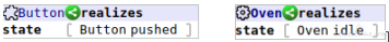 The above 2 behavior nodes are extracted from a BT modeling a oven. The left side says that a component ‘Button’ realizes the state ‘pushed’, the right side says the system component ‘Oven’ realizes the state ‘idle’.
 - Wait for signal - Component / System waits until the specified signal / event is received
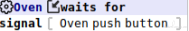 The above behavior node says that the system component ‘Oven’ waits for a signal ‘push button’. Note that, a signal may be generated internally from in the system boundary, or generated from environment. During modeling, we don’t need to specify this information, alternatively, the model checker will assign such information to each node intelligently.
 - Send signal - Component / System sends the specified signal
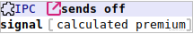 The above behavior node is extracted from a BT modeling a Insurance Premium Calculator, once the premium is calculated, the system sends off a signal (to environment) saying that the premium is calculated with the calculated premium as the payload.
 - Guard - Component / System waits until the specified condition is true
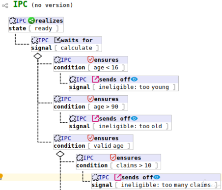
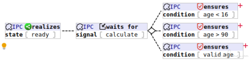 In the above partial BT, the 3 nodes at right side all are guards, after the IPC receiving a calculation request, it first checks the age of the policy holder to see if the age is valid or not. Note that the little red plus + means child nodes are collapsed, they are not part of the guard nodes.
 - Select state - Allow thread to continue if condition is true, otherwise, kill the thread it resides This node type is rarely used, so we have no example here as of now.
- Anchor - Anchor has no behavior, however, it provides a port to enable other nodes refer to it
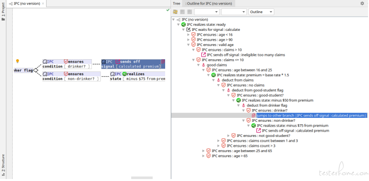
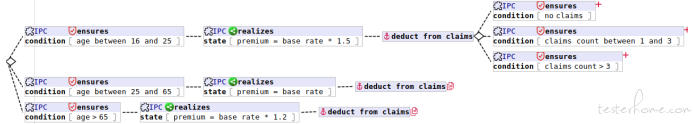 An anchor node ‘deduct from claims’ is shown above, and you can also see that 2 other nodes are referring to it (the two nodes with a little red copy icon , they are jump nodes, we will describe jump nodes later soon), this enables a type of node reuse. In above example, since the calculation logic after age deduction are shared by the 3 branches, we can write down the logic in the first branch, and let the other branches refer to it, so we don’t need to copy/paste, or re-type those nodes again and again.
#### Operator node types
An anchor node ‘deduct from claims’ is shown above, and you can also see that 2 other nodes are referring to it (the two nodes with a little red copy icon , they are jump nodes, we will describe jump nodes later soon), this enables a type of node reuse. In above example, since the calculation logic after age deduction are shared by the 3 branches, we can write down the logic in the first branch, and let the other branches refer to it, so we don’t need to copy/paste, or re-type those nodes again and again.
#### Operator node types - Reverse - Loop back to an ancestor node, and kill all sibling branches
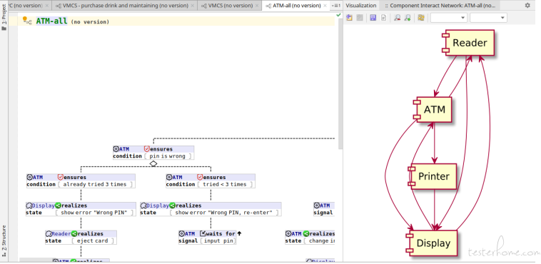
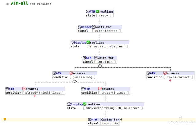 This depicts the login validation part of an ATM benchmark, the reverse node (it has a up arrow icon) saying that when customer enters a wrong PIN, and he/she has tried < 3 times, the customer still has more chance to re-enter the PIN, so this node guides the control loop back to ‘input pin’ node.
 - Reverse beyond root - Just like a reverse node, but reverse to an ancestor node which resides in some upstream BT
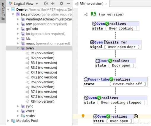 The above screenshot shows the modeling structure of the oven requirements. There are a few requirements named R1, R2, ..., R8, each requirement is modeled by a BT. The BT for R5 is showing, and there’s a reverse beyond root node at the bottom, the reverse target node ‘Oven open’ is not in BT for R5, but actually in BT for R6. During modeling, you don’t need to remember those details, you just translate the requirements written in natural language literally to BTs, and later, an almost automatic composition procedure can take all those BTs and integrate them together to form the big picture.
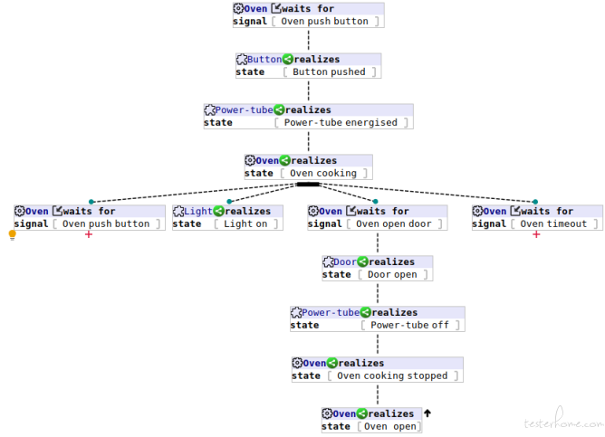
Below shows the part of the integrated BT (note that the reverse beyond root of BT for R5 has been refined to be a reverse node automatically, because the reverse target now can be found in this integrated BT):
The above screenshot shows the modeling structure of the oven requirements. There are a few requirements named R1, R2, ..., R8, each requirement is modeled by a BT. The BT for R5 is showing, and there’s a reverse beyond root node at the bottom, the reverse target node ‘Oven open’ is not in BT for R5, but actually in BT for R6. During modeling, you don’t need to remember those details, you just translate the requirements written in natural language literally to BTs, and later, an almost automatic composition procedure can take all those BTs and integrate them together to form the big picture.
Below shows the part of the integrated BT (note that the reverse beyond root of BT for R5 has been refined to be a reverse node automatically, because the reverse target now can be found in this integrated BT):
- Kill - Terminate all behaviors associated with the target tree This node type is also rarely been used, so no example can be provided as of now.
- Synchronisation - Wait for other participating nodes
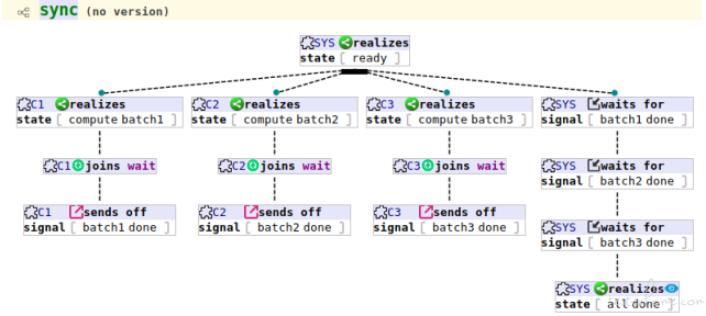 Though we have no real scenario which uses synchronisation nodes, the above BT shows a simple concurrent batch job scenario:
3 worker threads compute the batches 1, 2, and 3, when they complete their batch separately, they join a ‘wait’ synchronisation group, so when they are all done, they send the ‘done’ signal, and the main thread (at right most) waits for all the 3 ‘done’ signal, and then sends ‘all done’ signal to environment.
Though we have no real scenario which uses synchronisation nodes, the above BT shows a simple concurrent batch job scenario:
3 worker threads compute the batches 1, 2, and 3, when they complete their batch separately, they join a ‘wait’ synchronisation group, so when they are all done, they send the ‘done’ signal, and the main thread (at right most) waits for all the 3 ‘done’ signal, and then sends ‘all done’ signal to environment. - Jump - Behave as the target tree We already see this node type in action when we introduce anchor node type above, so we will not say more here.
Branching types
◼ Alternative branching - Pass control to only one of the child nodes. If multiple choices are possible, make a non-deterministic choice.
◼ Parallel branching - Pass control to all child nodes concurrently.
You have seen many examples of branching in the above screenshots, generally speaking, alternative branching will pick up one and only one child node to pass control to, and parallel branching will pass control to all child nodes concurrently. The node takes alternative branching has a diamond attached to, and the node takes parallel branching has a black bar attached to.
We respect your data...
Every QA has his/her own set of secret data to support his/her daily test execution tasks. In the MBTtester's modeler, data constraints can be fed to each input event node types, as below screenshot shows (a behavior node's inspector window):
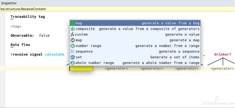
A few data constraint types you can attach:
◼ bag - a value list, the backend engine will choose a value randomly from this list whenever it needs a value.
◼ number range - a range of real numbers, the backend engine will choose a value randomly from this range whenever it needs a value.
◼ whole number range - just like number range, but this range only contains whole numbers (integers).
◼ sequence - a sequence, modeler can control the length of this sequence, and how each element should be generated (using sub-constraints).
◼ set - like sequence, but set is orderless and elements are distinct from each other.
◼ map - a dictionary structure, each key in this map has a separate data generator, modeler can control how many keys in the map, which keys are optional, which keys should be present together, and which keys should be mutual exclusive.
◼ custom - generate value from modeler defined function.
◼ composite - a composite data generator with a list of data generators, the backend engine will choose a data generator randomly to use whenever it needs a value.
For example, say we have a behavior node which takes the customer ‘age’ as an input parameter, a whole number range is enough (assume in our requirement, age takes
value from range [0,131]):
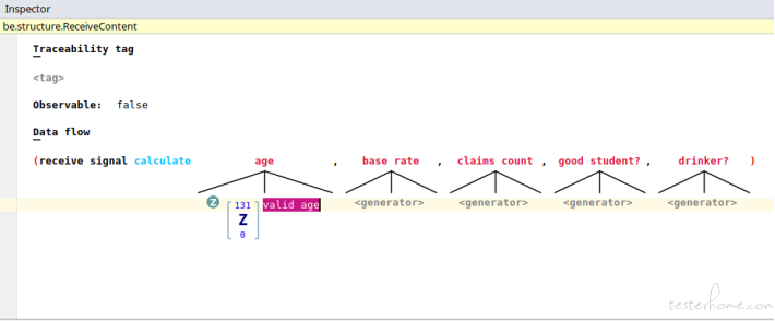
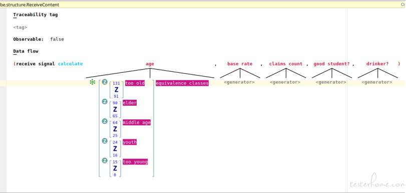
Note that we attach a tag ‘valid age’ to this whole number range, this is optional, however, the tags can serve as the classifier for equivalence classes, as we all know, equivalence class partitioning is an important technique widely used by QAs. For example, we could design the data generators for ‘age’ parameter as below (a composite data generator with 5 child whole number range generators corresponding to the 5 equivalence classes of ‘age’ parameter). But to make this example easily to be followed, we just use the singleton range [0,131] as above shows.
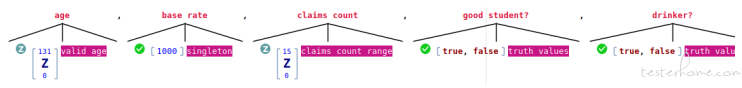
As a final example, below screenshot shows all input parameters are decorated by their respective data constraints:
How to provide bidirectional traceability matrix between requirements and test artifacts?
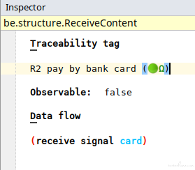
As we've mentioned above, every behavior node can be assigned a traceability tag (a requirement ID, for example):
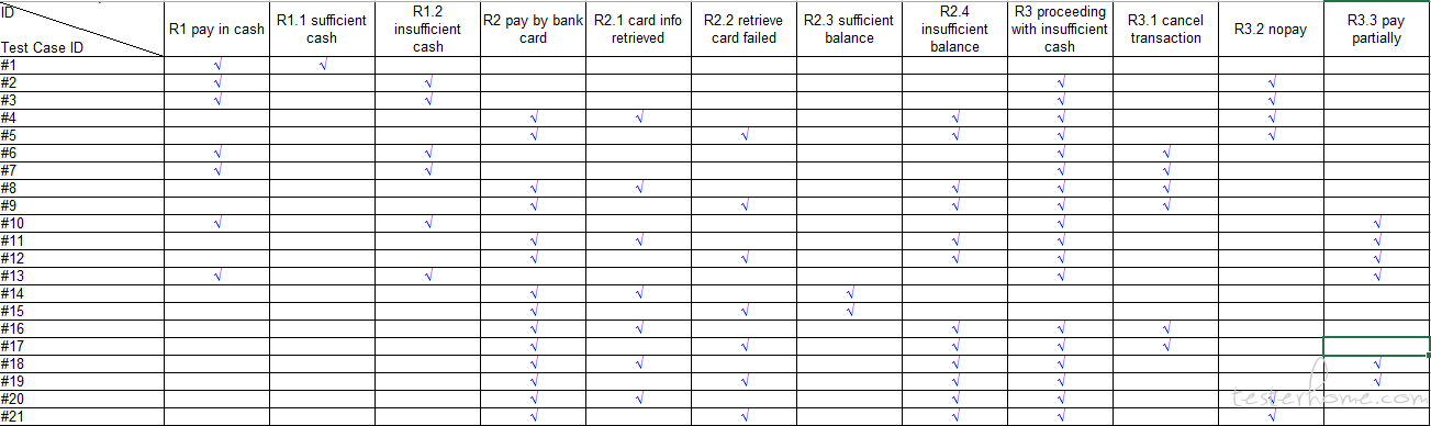
From those metadata, traceability matrix can be easily generated, a piece of a cake:
Model comprehension
Before generating testing related artifacts, only the behavior tree itself can provide you many benefits. You can communicate with the project stakeholders using this graphical model, especially with those from business background, since the behavior tree is easy to understand, and unambiguity. This means you can start to model the requirement as early as you can, and get feedback from business at the early stage.
Additionally, there are a few utilities you can use to gain more insights into the BTs, thus the requirements. Here we will give each a glance.
Activity diagram from BTs
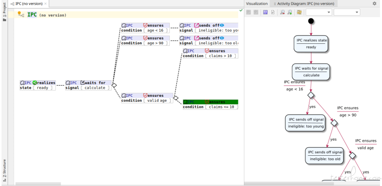
You can generate activity diagram from BT, many people understand activity diagram, hence this can help them view the requirement from a different aspect.
Component Interact Network of BTs
For a behavior tree with many subjects work together, a Component Interact Network (CIN). Below is an example of modeling an ATM benchmark.
Outlining BTs
If you prefer the more traditional tree structure, you can outline the requirement tree. You can make any node as root in the outline, so you can zoom-in/zoom-out in the tree hierarchy.
Filtering nodes by subjects
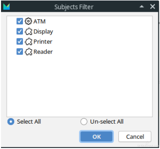
In case that you are interested in only the behaviors of a specific component, you can filter the nodes related (below shows only the behavior nodes related to card reader in the ATM model). Below is the list of all components in the ATM model:
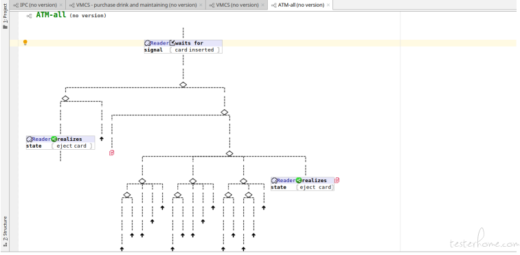
Below screenshot shows the filtered behavior nodes when only subject ‘Reader’ is selected:
View BTs in different layouts
The default layout of a BT is a top-down tree like structure. When different layout is desired, you can right click on any behavior node, and select Behavior Tree Layout menu to call out the layout configuration dialog for the node:
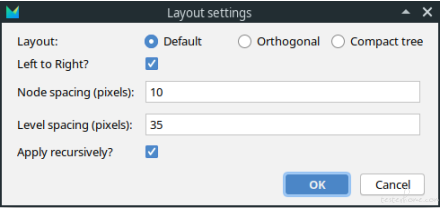
In this dialog, 3 layout types are provided: Default, Orthogonal, and Compact tree. You can also ask a different layout direction other than top-down, i.e. if the ‘Left to Right?’ choice is selected, the layout manager will layout the tree nodes from left to right instead of from top to down. The node spacing and level spacing provide you fine-grained control of spacing of nodes and levels. If ‘Apply recursively?’ is not selected, the configuration will apply to the behavior node you selected only, otherwise, the configuration will apply to all descendants. Below is an example of left-to-right Compact tree layout:
Generate some goods
After modeling your requirement into behavior trees, and perhaps, integrated a few related trees into a big one, you can fed the behavior tree into our backend engine to generate full suite of manual test cases, automated test scripts (currently, only selenium in JAVA is supported, more bridges are under heavy development).
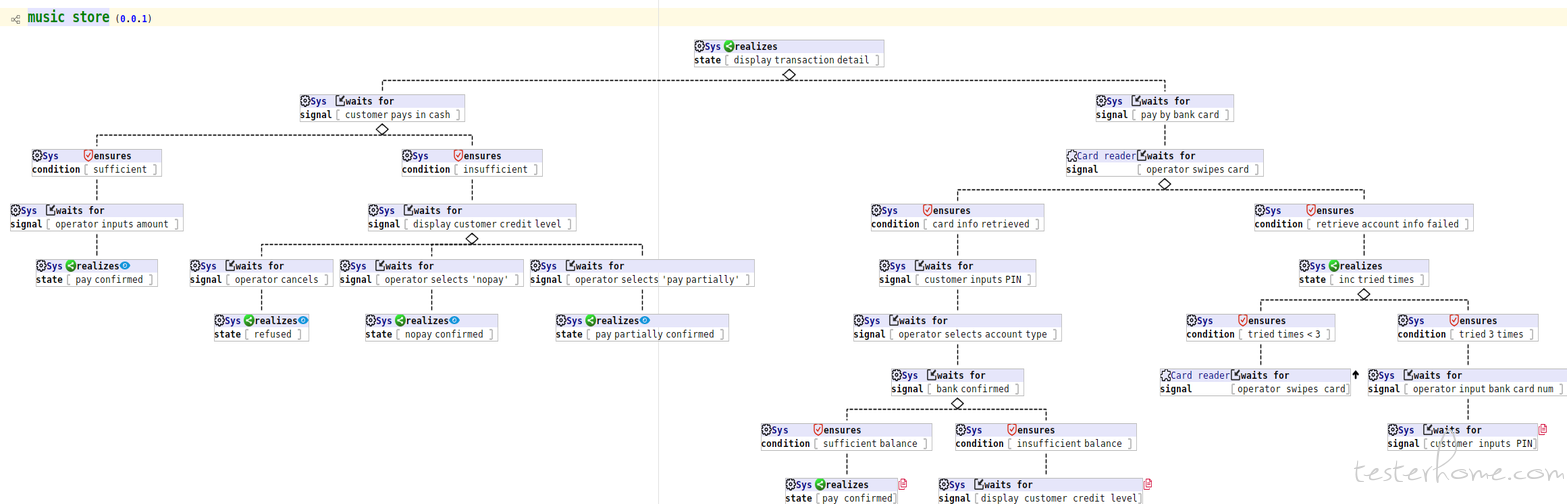
A sample behavior tree model
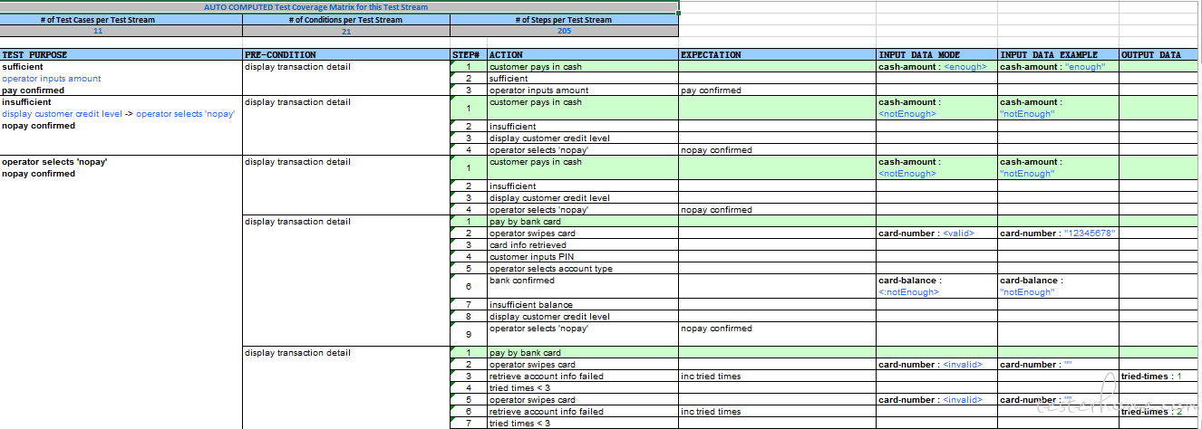
A sample of manual test suite with test data generated
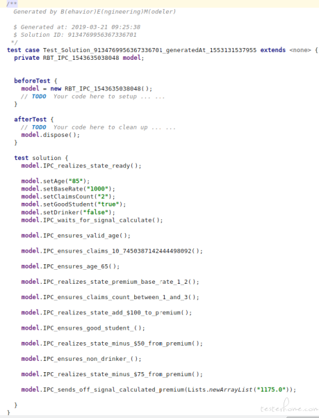
A sample of automated test script
The traceability matrix
You already saw it above, no repeat here.
Summary
We've applied this tool in a few internal real projects, it shows its value, much much value. Maybe in a later opportunity, I will show you an example.
Well, we have finished this short introduction. Many are not covered yet, but we believe that it should give you enough information about this tool.
If you have any idea, suggestions, comments, whatever :-), please tell us, we will be happy to hear from you!
If you have reached here... you may also want to see more of MBTester.